


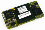
X-MAX-1 und X-MAX-E
X-MAX-1 und X-MAX-E
- CPU module
- 468-CPU up to 100 MHz
- Up to 16 MByte RAM
- 4, 8 or 16 MByte Flash-ROM
- 10BaseT interface
- Serial RS-232 and parallel port
- Keyboard-Interface
- 4 Timer
- Time and date
- Watch-Dog and NMI logic
- Initialization data in EEPROM
- Graphic controller for LCD operation
- PCMCIA controller for 2 PC cards
- Real-Time-Multi-Tasking operating system on-board
- Suitable for Windows CE
Description
The X-MAX-1 module is fitted with a 486 CPU with 8 KByte cache. The clock frequency of the local CPU is currently between 33 MHz and 100 MHz (internal), depending on the version.
The X-MAX-1 module is already fitted with extensive peripheral facilities. In addition to the Flash EPROM and RAM (of up to 16 Mbyte each) it has 4 timers, interrupt and DMA controller, a serial RS-232 interface with all modem control lines and a printer interface, a clock, a watchdog and voltage monitor. The clock can be buffered by an external battery. All interfaces are PC compatible.
The Flash EPROM on the X-MAX-1 module contains the OsX real-time multi-tasking operating system for up to 1024 tasks. Real-time programs for tasks such as measured data acquisition, control, PID controllers, function generators or FFTs are included with the module. Complete PLC protocols such as Siemens 3964/R, GE Fanuc and PROFIBUS are also available for serial communication.
Further CPU modules with even more powerful processors are under development, for instance with a strong ARM CPU. These CPU modules can be mixed in any combination on a MAX6pci carrier card. The carrier card can also be used in what is called "stand-alone" mode. In this case the application programs are in the Flash ROM of one of the modules, e.g. an X-MAX-1. Communication with the host computer then takes place via, for instance, a serial interface (RS-232, RS-485 etc.) or ethernet.
It is also possible to write your own real-time programs for the card, working in the familiar PC development environment.
Specifications
| CPU | 486-100, 486-33 |
| RAM | 2 MByte up to 16 MByte |
| ROM | Flash-EPROM, 4 MByte up to 16 MByte |
| EEPROM | 4kByte, serial |
| Timer | 3 x 16 Bit, input frequency 1,1892 MHz, Timer A and C can trigger interrupt, real-time clock. |
| Interrupts | 15 Inputs, 4 from X-Bus, 1 from Mailbox-Register, 2 from external inputs, 2 from timer, 1 from serial interface, 1 from clock |
| Serial interfaces | RS-232 interface, 16550-kompatibel |
| real-time clock | Date (day, month, year, week) and time (hours, minutes, seconds), battery buffering possible, capable of generating interrupts |
| Multi-tasking operating system | Full real-time capable, 1024 tasks, interrupt, timer initiated and non interrupt tasks, in EPROM of base board, copied to RAM, uses 64 KB RAM |
| Power consumption | +3,3 V: 594 mA (typ. at 100 MHz) |
| Dimensions | 29 x 58 x 8 mm |
| Operating temperature range | 0 to 55°C (optional –40° to +85° C) |
| Humidity condition | 5 to 95% (not condensing) |